AutoCAD Tips & Tutorials
Tutorial: Draw a 3D threaded bolt
A common
I rummaged around a box of
miscellaneous junk and found this bolt. You can see that it's about 3 inches
long.

Follow these steps:
1. Start a new drawing using
acad3d.dwt as the template. Set the visual style to 3D Wireframe
and the workspace to 3D Modeling.
2. Type plan
to see the view from the top.
3. Create a new layer
4. Start the POLYLINE command
- 3<180
- 3/16<90
- .5<0
- 1/4
- 2<0
- Close
Note: Close the polyline ensures that you'll get a solid rather than a
surface when you revolve. You'll need the solid for later operations

5. Start the REVOLVE command and
select the polyline. Revolve it along the 3-unit line
6. To get a fuller look

7. Just to see the result
8. Then
9. Start the UCS command and use the
View option to create a new UCS. If you want
10. Return to the SW Isometric
viewpoint again. You're still in the new UCS. This will help you create the
bolt's head.
11. Start the CYLINDER command. The
center should be the center of the revolved solid's top. Use the Diameter
option and set it to 9/16. The height is 0.25.
12. Create a polygon of 6 sides. The
center is the bottom center of the cylinder
13. Use the EXTRUDE command to extrude
the hexagon to the top of the cylinder.
14. To create the beveled top
15. Extrude it
16. Use the INTERSECT command and
choose the extruded

17. To create the threads
18. Switch to the World UCS and use the
PLAN command. Turn the viewpoint so that the end of the helix is at the top or
bottom. Below
19. To create the triangular shape of
the thread
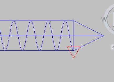
20. Start the SWEEP command and select
the triangle. Use the Alignment option and set it to No. Then select the helix
as the sweep path.
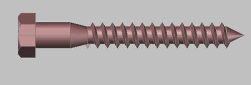
21. Use the UNION command to combine
all the objects. Here's the result in the 3D Hidden visual style.

Here's the result with the
Framing Steel material. I expected it to be silver but it came out coppery. It
looked so good that I left it.
For an excellent set of 3D
tutorials
Related tips:
- Tutorial:
Draw a 3D threaded bolt-video tutorial (See a
video of this tutorial!)
- 3D
Tutorial: Draw a glass
- Carve a solid with a surface
For more:
http://www.ellenfinkelstein.com/autocadtips/AutoCAD_tips_draw_3d_threaded_bolt.html